 Powerlink communication  I/O module object for Bernecker + Rainer
 Power supply units.

 The module object is configured below a Powerlink Controlled Node object
 in the Node hierarchy. This module object also contains input channels to
 be connected to signals in Plant hierarchy.
Configuration
 Place the object under a Powerlink controlled node object of class
 Epl_CN and connect the channels to signals in Plant hierarchy. The
 location under the Epl_CN object is dependent on the hardware
 configuration. See B&R Case Study below for more information.

 The Epl_CN object also needs an Epl_MN and an EplHandler object, see these
 objects for more information.
Example of a B&R Power Supply unit
 One example of a Power Supply unit working with object BR_PowerSupply_EplModule
 is the X20PS9400 (Fig 1) together with X20 Bus controller, in this case
 Powerlink Bus Controller X20BC0083 (Fig 2).

 Description and figures from B&R X20 System Manual.
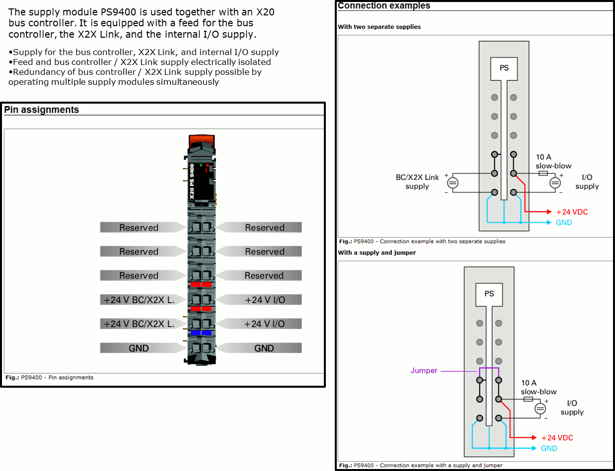
Fig 1 Pin assignment and connection example PS9400
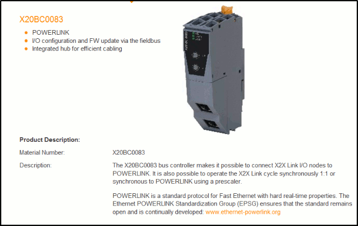
Fig 2 Bus Controller X20BX0083
B&R Case Study
 This study explain a lot of steps needed to configurate an X20 system with
 Powerlink communication to a ProviewR system. The case (Fig 3) is based on the
 B&R hardware:

 - X20 Bus Controller POWERLINK (Slave id = 15).
 - 24 VDC Powersupply unit.
 - 4 Digital input unit.
 - 4 Analog input unit, channel 01 is set to 0-20 mA.
 - 4 Analog output unit.

 All I/O hardware settings through FieldbusDESIGNER tool except Ai channel 01
 are default values, bus controller id is set to 15 (not necessary).
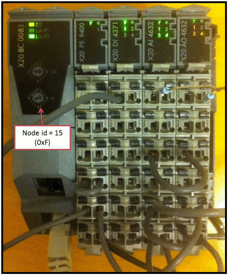
Fig 3 Photo Case Study hardware units, bus controller unit id is set to 15.
Short step by step description to configure a B&R X20 Powerlink controlled node (CN):
 - Use the Windows PC tool FieldbusDESIGNER from B&R to configure the hardware and
   create the XDC file (XML Device Configuration).

 - In a ProviewR project create and configure the ProviewR Powerlink objects and the B&R module
   objects corresponding to the X20 hardware configuration in FieldbusDESIGNER tool and
   openCONFIGURATOR tool. i.e. memory mapping and node id.

 - Use the Linux PC tool openCONFIGURATOR and import the XDC file from FieldbusDESIGNER
   to create and configure a new X20 Controlled node and create the mnobd.cdc
   binary file used by the Powerlink stack. Transfer the mnobd.cdc to $pwrp_load.

 - Build the ProviewR project and distribute.
FieldbusDESIGNER Tool (WINDOWS PC)
 Example 1 below shows the hardware solution in this Case Study i.e. all IO modules,
 Power supply and Bus controller are created. After the hardware configuration is done
 and the node adress is set to 15 (not necessary) the project is built to create the XDC
 file, in this case 0100006C_X20BC0083_15.xdc (suffix 15 = node id). Example 2 shows the
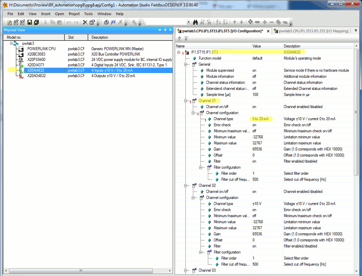
 I/O configuration for the analog inputs, channel 01 and 02.
Example 1 Windows PC tool Fielbus Designer from B&R
Hardware configuration in the B&R Case study, units are marked with yellow color.
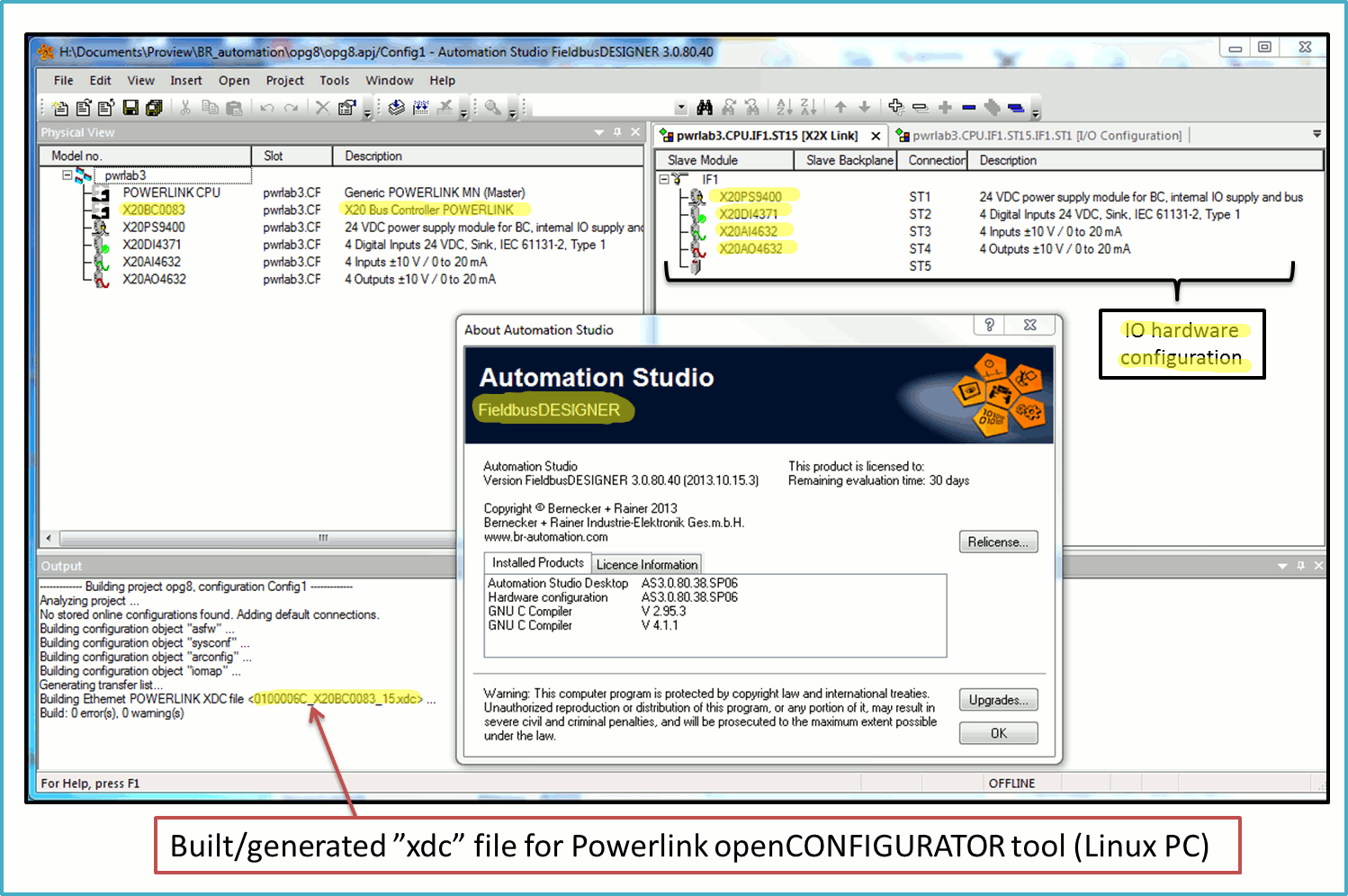
Example 2 I/O configuration of analog inputs
 Yellow marked Channel 01 value 'channel type' is changed to 0-20 mA,
 default value is +/- 10 V.
ProviewR
 The B&R Case Study contains a ProviewR project ACS880Pn and one MN and two CN nodes.
 The first CN node is an ABB frequency converter ACS880 and the second is B&R Bus
 Controller node. The Examples 10-13 below shows the ProviewR settings.
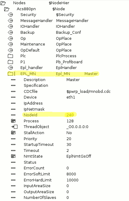
Example 10 Settings in ProviewR Powerlink MN node
 Settings needed in ProviewR class Epl_MN node. Node id
 for MN node is always 240.
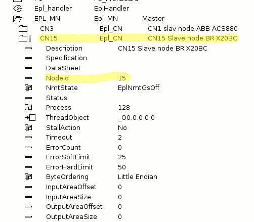
Example 11 Settings in ProviewR node CN
 Settings needed in ProviewR for class Epl_CN. The 'NodeId'
 shall be the same as in the openCONFIGURATOR, i.e. 15, see
 also example 15 below.
Example 12 Create 'IO mapping' modules
 Modules needed in ProviewR to match the I/O mapping, i.e. hardware
 configuration in FieldbusDESIGNER tool, see also example 1.

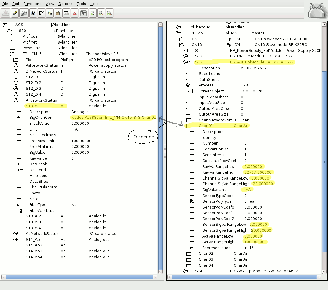
Example 13 Connect IO and Channel settings
 All the used channels in modules ST1, ST2, ST3 and ST4 shoud be connected
 to signals in the plant hierarchy with the 'IO Connect' function. In this
 case also the ST3 analog input O1 settings is changed to 0-20 mA and connected
 to signal ST3_Ai1. See also example 2.
openCONFIGURATOR Tool (Linux PC)
 openCONFIGURATOR is an open source tool contributed by www.kalycito.com.
 openCONFIGURATION is used for easy setup, configuration and maintenance
 of any POWERLINK network. openCONFIGURATOR ideally complements openPOWERLINK,
 the open source POWERLINK protocol stack for master and slave nodes.

 Every node in a Powerlink network must be configured in this tool.
 In a ProviewR project all Powerlink CN nodes memory mapping is a reflection
 of the memory mapping in a openCONFIGURATOR project.

 From the openCONFIGURATOR tool a CDC file is generated. This file is used by
 the Powerlink stack. The name of the cdc-file shall be specified in the Epl_MN
 object, attribute CDCfile. The default name is $pwrp_load/mnodb.cdc.

 A Powerlink network consists of two device types, MN (Managing Node)
 and one or several CN (Controlled Node).

 Note It is recommended to study the help in the openCONFIGURATOR tool and a detailed
 Case Study in ProviewR class help for class object ABB_ACS880_Epl, see link below.
Short description step by step:
   - Use the popup menu for an object of class Epl_MN to start openCONFIGURATOR tool.
   - Open existing or a new project.
   - Create a new CN node and import the 0100006C_X20BC0083_15.xdc file.
   - Build the project. This will generate the binary cdc-file.
   - Transfer cdc file to $pwrp_load folder.
   - In ProviewR distribute function a copy command is needed for file mnobd.cdc
Configuration
 Create a new CN node and import the 0100006C_X20BC0083_15.xdc file generated
 from tool FieldbusDESIGNER. This file is prepared with all memory mapping
 (TPDO, RPDO) needed for the ProviewR class object BR_Di4_EplModule,
 BR_PowerSupply_EplModule, BR_Ai_EplModule and BR_Ao4_EplModule. Build the
 project with project settings "auto generate" set to YES, then transfer the
 new mnobd.cdc file to ProviewR project $pwrp_load folder.

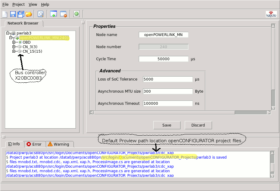
 Example 14 to 17 below shows some screenshots from openCONFIGURATOR tool.
Example 14
 The figure shows the openCONFIGURATOR settings for master MN node and
 default path for project files. The two CN nodes is also visible in the
 figure, CN_15 is the B&R bus controller slave node.
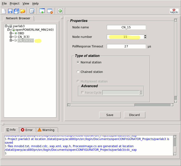
Example 15
 openCONFIGURATOR settings for slave node 15, i.e. Bus Controller X20BC0083.
 This Id must be the same as in the ProviewR object Epl_CN, see also example 11.
Example 16
 Memory mapping settings TPDO, reads data from the B&R bus controller, i.e. Power Supply,
 Di, Ai and Ao in this order. For example the yellow marked address 0x2102 is the
 address specification for analog input X20AI4632 slot ST3. Note that the Ao unit
 X20AO4632(0x2003) slot ST4 also is mapped here becouse the unit have one input ChanIi
 ChanNetworkStatus attribute.

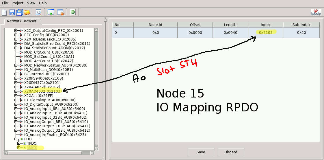
Example 17
 Memory mapping settings RPDO, writes data to the B&R bus controller, i.e. Ao word. The
 yellow marked address 0x2103 is the analog output X20AO4632 slot ST4.
See also


